
Amazing video that all must watch
Month: November 2016
mangalyan to mars
ISRO seeking scientific proposals for Mars Orbiter Mission-2 following Mangalyaan’s success


Mars Orbiter Mission
Zee Media Bureau
New Delhi: The government on Friday said that the Indian Space Research Organisation(ISRO) is seeking scientific proposals forMars Orbiter Mission-2 (MOM-2) to expand inter-planetary research.
Ads b
Jitendra Singh, Union Minister of State in the Prime Minister’s Office that looks after the Department of Space, said in a written response to a question in Rajya Sabha, that the configuration, objectives and scientific experiments of MOM-2 is yet to be formulated.
“A call for proposals through an Announcement of Opportunity (AO) has been made within India to seek proposal for scientific experiments for Mars Orbiters Mission-2,” Mr Singh said.
After the successful launch and orbit of Mars by its first probe Mangalyaan, the Mars Orbiter Mission (MOM), ISRO had said announced their plans to return to the Red Planey with the second mission.
Mangalyaan, which is India’s first interplanetary mission, was successfully inserted into Mars orbit on 24 September 2014 after a 298-day transit to the Red Planet.
The Indian Mars probe has completed 25 months in orbit and is presently functioning satisfactorily.
If all goes according to plan, ISRO will launch Mangalyaan-2 to Mars by 2020, which will consist of an orbiter,
AGEING AND HEALING
New research clarifies why wounds heal more slowly with age

Acting older: Five days after an injury to young mouse skin (blue), new skin cells (green) fill the wound (top). When researchers turned down expression of a protein skin cells use to talk to nearby immune cells, new skin took much longer to arrive (bottom).
Older bodies need longer to mend. This reality of aging has been documented since World War I, with the observation that wounds heal slower in older soldiers. Yet until now, researchers have not been able to tease out what age-related changes hinder the body’s ability to repair itself.
Recent experiments at The Rockefeller University explored this physiological puzzle by examining molecular changes in aging mouse skin. The results, described November 17 in Cell, delineate a new aspect of how the body heals wounds.
“Within days of an injury, skin cells migrate in and close the wound, a process that requires coordination with nearby immune cells. Our experiments have shown that, with aging, disruptions to communication between skin cells and their immune cells slow down this step,” saysElaine Fuchs, the Rebecca C. Lancefield Professor and head of the Robin Chemers Neustein Laboratory of Mammalian Cell Biology.
“This discovery suggests new approaches to developing treatments that could speed healing among older people,” adds Fuchs, who is also a Howard Hughes Medical Institute investigator.
Return of the skin cells
Whenever a wound occurs, the body needs to repair it quickly to restore its protective skin barrier. “Wound healing is one of the most complex processes to occur in the human body,” says Brice Keyes, a former postdoc in Fuch’s lab and currently a researcher at Calico Life Sciences. “Numerous types of cells, molecular pathways, and signaling systems go to work over timescales that vary from seconds to months. Changes related to aging have been observed in every step of this process.” Keyes and Siqi Liu, an immunology specialist and a current Jane Coffin Childs postdoctoral fellow in in the lab, are co-first authors of the Cell article.
Both skin cells and immune cells contribute to this elaborate process, which begins with the formation of a scab. New skin cells known as keratinocytes later travel in as a sheet to fill in the wound under the scab.
The team focused on this latter step in healing in two-month-old versus 24-month-old mice—roughly equivalent to 20- and 70-year-old humans. They found that among the older mice, keratinocytes were much slower to migrate into the skin gap under the scab, and, as a result, wounds often took days longer to close.
Wound healing is known to require specialized immune cells that reside in the skin. The researchers’ new experiments showed that following an injury, the keratinocytes at the wound edge talk to these immune cells by producing proteins known as Skints that appear to tell the immune cells to stay around and assist in filling the gap. In older mice, the keratinocytes failed to produce these immune signals.
Seeking a reversal
To see if they could enhance Skint signaling in older skin, the researchers turned to a protein that resident immune cells normally release after injury. When they applied this protein to young and old mouse skin tissue in a petri dish, they saw an increase in keratinocyte migration, which was most pronounced in the older skin. In effect, the old keratinocytes behaved more youthfully.
The scientists hope the same principle could be applied to developing treatments for age-related delays in healing.
“Our work suggests it may be possible to develop drugs to activate pathways that help aging skin cells to communicate better with their immune cell neighbors, and so boost the signals that normally decline with age,” Fuchs says.
This research was supported by the National Institutes of Health (grant R01-AR050452) and the Ellison Foundation
Make a Mini CNC Plotter with old DVD players Arduino and L293D
Drastic climate changes
EARTH TO MARS NEW JOURNEY…..
WIRELESS POWER TRANSMISSION (older history)
Tesla
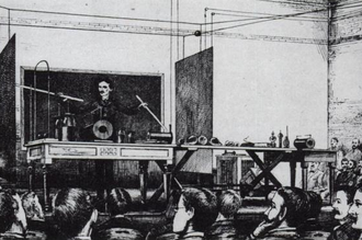
Tesla demonstrating wireless transmission by “electrostatic induction” during an 1891 lecture at Columbia College. The two metal sheets are connected to a Tesla coil oscillator, which applies high-voltage radio frequency alternating current. An oscillating electric field between the sheets ionizes the low-pressure gas in the two long Geissler tubes in his hands, causing them to glow, similar to neon tubes.
After 1890 inventor Nikola Tesla experimented with transmitting power by inductive and capacitive coupling using spark-excited radio frequency resonant transformers, now called Tesla coils, which generated high AC voltages.[35][37][105] Early on he attempted to develop a wireless lighting system based on near-field inductive and capacitive coupling[37] and conducted a series of public demonstrations where he lit Geissler tubes and even incandescent light bulbs from across a stage.[37][105][106] He found he could increase the distance at which he could light a lamp by using a receiving LC circuit tuned to resonance with the transmitter’s LC circuit.[36] using resonant inductive coupling.[37][38] Tesla failed to make a commercial product out of his findings[107] but the resonant inductive coupling used is now a familiar technology used throughout electronics and is currently being widely applied to short-range wireless power systems.[37][108]
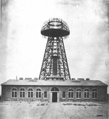
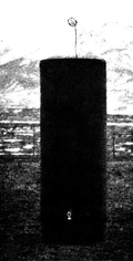
(left) Experiment in resonant inductive transfer by Tesla at Colorado Springs 1899. The coil is in resonance with Tesla’s magnifying transmitter nearby, powering the light bulb at bottom. (right) Tesla’s unsuccessful Wardenclyffe power station.
 Tesla went on to develop a wireless power distribution system that he hoped would be capable of transmit power long distance directly into homes and factories. Early on he seemed to borrow from the ideas of Mahlon Loomis,[109][110] proposing a system composed of balloons to suspend transmitting and receiving electrodes in the air above 30,000 feet (9,100 m) in altitude, where he thought the pressure would allow him to send high voltages (millions of volts) long distances. To further study the conductive nature of low pressure air he set up a test facility at high altitude in Colorado Springs during 1899.[111][112][113] Experiments he conducted there with a large coil operating in the megavolts range, as well as observations he made of the electronic noise of lightning strikes, led him to incorrectly conclude[114][115] that he could use the entire globe of the Earth to conduct electrical energy. The theory included driving alternating current pulses into the Earth at its resonant frequency from a grounded Tesla coil working against an elevated capacitance to make the potential of the Earth oscillate. Tesla thought this would allowing alternating current to be received with a similar capacitive antenna tuned to resonance it at any point on Earth with very little power loss.[116][117][118] His observations also led him to believe a high voltage used in a coil at an elevation of a few hundred feet would “break the air stratum down”, eliminating the need for miles of cable hanging on balloons to create his atmospheric return circuit.[119][120] Tesla would go on the next year to propose a “World Wireless System” that was to broadcast both information and power worldwide[121][122] and attempted in 1901 to construct a large high-voltage wireless power station, now called the Wardenclyffe Tower, at Shoreham, New York. By 1904 investment dried up and the facility was never completed.
ADRUINO PROJECT
|
For this project you will need: Part list for beginners:
|
   
|
Part list for ‘pro’ :
- ATmega328p (with Arduino Bootloader)*
- 28 pin DIP IC Socket
- 16MHz Crystal Oscillator
- 2x 22pF and 1x 100nF capacitors
- 10K resistor
- USB to Serial adapter**
- 2x L293D ICs
- Mini Servo Motor
- 2x DVD/CD Drives
- Prototyping PCB Circuit Board Stripboard
- 4x 2pins Screw Terminal Connector (or 2x 4 pins Screw Terminal Connector)***
*You will need also an Arduino UNO board to program the ATmega328 micro possessor
**USB to Serial adapter will allow the circuit to communicate with the computer through the USB cable, just like Arduino uno does.
***Why to use screw terminal connectors? Because you don’t want to solder and desolder cables from stepper motors until you find the correct working combination.
Tools (only for ‘pro’ part list):
- Screwdriver
- Soldering iron
- Solder
- Cutting tool (e.g. Dremel) (Optional for cutting plastic parts)
- Glue
 First step to start building this cnc machine is to disassemble two dvd/cd drives and take off them the stepper motors. Use the screwdriver to open them and take off them the rails. Next step is to choose our base for this CNC machine. I used one surface from remaining dvd ‘garbage’ stuff.Finally we will need to find something to attach the one of the stepper-rails vertically to our construction. (you will understand what I mean in our next step) Watch the above image.adruino video
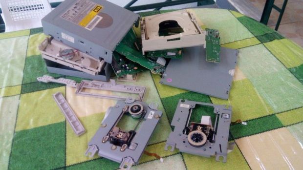
my first college project
hi I m Kishore and I m planning to do my first college project with my friends….my projects is about 2d printers
For the circuit you will need:
Part list for beginners:
- Arduino uno
- Breadboard
- 2x L293D ICs Motor driver
- Mini Servo Motor
- 2x DVD/CD Drives
Part list for ‘pro’ :
- ATmega328p (with Arduino Bootloader)*
- 28 pin DIP IC Socket
- 16MHz Crystal Oscillator
- 2x 22pF and 1x 100nF capacitors
- 10K resistor
- USB to Serial adapter**
- 2x L293D ICs
- Mini Servo Motor
- 2x DVD/CD Drives
- Prototyping PCB Circuit Board Stripboard
- 4x 2pins Screw Terminal Connector (or 2x 4 pins Screw Terminal Connector)***
*You will also need an Arduino UNO board to program the ATmega328 micro controller.
**USB to Serial adapter will allow the circuit to communicate with the computer through the USB cable, just like Arduino uno does.
***Why to use screw terminal connectors? Because you don’t want to solder and desolder cables from stepper motors until you find the correct working combination!
For the mounting base:
- One piece of plexiglass 20×16 cm (thickness 5mm) (for X axis)
- Two pieces of plexiglass 14×4 cm (thickness 5mm) (for Y axis)
- A few nut screws, nuts and shims (~20)
- A few spacers
- Four supporting angles (preferably plastic)
Instead of plexiglass you can also use wood, metal or parts from dissasembly cd/dvd drives
Tools:
- Screwdriver
- Soldering iron
- Solder
- Drill
- Cutting tool (e.g. Dremel) (Optional for cutting plastic/plexiglass parts)
- Glue
click thislink CNC plotter to see the video of it
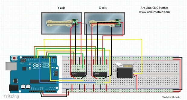
CODE FOR CNC PLOTTER:
#include <Stepper.h>
#define LINE_BUFFER_LENGTH 512
// Should be right for DVD steppers, but is not too important here
const int stepsPerRevolution = 20;
// create servo object to control a servo
// Initialize steppers for X- and Y-axis using this Arduino pins for the L293D H-bridge
Stepper myStepperY(stepsPerRevolution, 2,3,4,5);
Stepper myStepperX(stepsPerRevolution, 6,7,8,9);
Stepper myStepperZ(stepsPerRevolution, 10,11,12,13);
/* Structures, global variables */
struct point {
float x;
float y;
float z;
};
// Current position of plothead
struct point actuatorPos;
// Drawing settings, should be OK
float StepInc = 1;
int StepDelay = 0;
int LineDelay = 50;
int penDelay = 50;
// Motor steps to go 1 millimeter.
// Use test sketch to go 100 steps. Measure the length of line.
// Calculate steps per mm. Enter here.
float StepsPerMillimeterX = 6;
float StepsPerMillimeterY = 6;
// Drawing robot limits, in mm
// OK to start with. Could go up to 50 mm if calibrated well.
float Xmin = 0;
float Xmax = 40;
float Ymin = 0;
float Ymax = 40;
float Zmin = 0;
float Zmax = 30;
float Xpos = Xmin;
float Ypos = Ymin;
float Zpos = Zmax;
// Set to true to get debug output.
boolean verbose = false;
// Needs to interpret
// G1 for moving
// G4 P300 (wait 150ms)
// M300 S30 (pen down)
// M300 S50 (pen up)
// Discard anything with a (
// Discard any other command!
/**********************
* void setup() – Initialisations
***********************/
void setup() {
// Setup
Serial.begin( 9600 );
// Decrease if necessary
myStepperX.setSpeed(60);
myStepperY.setSpeed(60);
myStepperZ.setSpeed(50);
// Set & move to initial default position
// TBD
// Notifications!!!
Serial.println(“Mini CNC Plotter alive and kicking!”);
Serial.print(“X range is from “);
Serial.print(Xmin);
Serial.print(” to “);
Serial.print(Xmax);
Serial.println(” mm.”);
Serial.print(“Y range is from “);
Serial.print(Ymin);
Serial.print(” to “);
Serial.print(Ymax);
Serial.println(” mm.”);
}
/**********************
* void loop() – Main loop
***********************/
void loop()
{
delay(200);
char line[ LINE_BUFFER_LENGTH ];
char c;
int lineIndex;
bool lineIsComment, lineSemiColon;
lineIndex = 0;
lineSemiColon = false;
lineIsComment = false;
while (1) {
// Serial reception – Mostly from Grbl, added semicolon support
while ( Serial.available()>0 ) {
c = Serial.read();
if (( c == ‘\n’) || (c == ‘\r’) ) { // End of line reached
if ( lineIndex > 0 ) { // Line is complete. Then execute!
line[ lineIndex ] = ‘\0’; // Terminate string
if (verbose) {
Serial.print( “Received : “);
Serial.println( line );
}
processIncomingLine( line, lineIndex );
lineIndex = 0;
}
else {
// Empty or comment line. Skip block.
}
lineIsComment = false;
lineSemiColon = false;
Serial.println(“ok”);
}
else {
if ( (lineIsComment) || (lineSemiColon) ) { // Throw away all comment characters
if ( c == ‘)’ ) lineIsComment = false; // End of comment. Resume line.
}
else {
if ( c <= ‘ ‘ ) { // Throw away whitepace and control characters
}
else if ( c == ‘/’ ) { // Block delete not supported. Ignore character.
}
else if ( c == ‘(‘ ) { // Enable comments flag and ignore all characters until ‘)’ or EOL.
lineIsComment = true;
}
else if ( c == ‘;’ ) {
lineSemiColon = true;
}
else if ( lineIndex >= LINE_BUFFER_LENGTH-1 ) {
Serial.println( “ERROR – lineBuffer overflow” );
lineIsComment = false;
lineSemiColon = false;
}
else if ( c >= ‘a’ && c <= ‘z’ ) { // Upcase lowercase
line[ lineIndex++ ] = c-‘a’+’A’;
}
else {
line[ lineIndex++ ] = c;
}
}
}
}
}
}
void processIncomingLine( char* line, int charNB ) {
int currentIndex = 0;
char buffer[ 64 ]; // Hope that 64 is enough for 1 parameter
struct point newPos;
newPos.x = 0.0;
newPos.y = 0.0;
// Needs to interpret
// G1 for moving
// G4 P300 (wait 150ms)
// G1 X60 Y30
// G1 X30 Y50
// M300 S30 (pen down)
// M300 S50 (pen up)
// Discard anything with a (
// Discard any other command!
while( currentIndex < charNB ) {
switch ( line[ currentIndex++ ] ) { // Select command, if any
case ‘U’:
penUp();
break;
case ‘D’:
penDown();
break;
case ‘G’:
buffer[0] = line[ currentIndex++ ]; // /!\ Dirty – Only works with 2 digit commands
// buffer[1] = line[ currentIndex++ ];
// buffer[2] = ‘\0’;
buffer[1] = ‘\0’;
switch ( atoi( buffer ) ){ // Select G command
case 0: // G00 & G01 – Movement or fast movement. Same here
case 1:
// /!\ Dirty – Suppose that X is before Y
char* indexX = strchr( line+currentIndex, ‘X’ ); // Get X/Y position in the string (if any)
char* indexY = strchr( line+currentIndex, ‘Y’ );
if ( indexY <= 0 ) {
newPos.x = atof( indexX + 1);
newPos.y = actuatorPos.y;
}
else if ( indexX <= 0 ) {
newPos.y = atof( indexY + 1);
newPos.x = actuatorPos.x;
}
else {
newPos.y = atof( indexY + 1);
indexY = ‘\0’;
newPos.x = atof( indexX + 1);
}
drawLine(newPos.x, newPos.y );
// Serial.println(“ok”);
actuatorPos.x = newPos.x;
actuatorPos.y = newPos.y;
break;
}
break;
case ‘M’:
buffer[0] = line[ currentIndex++ ]; // /!\ Dirty – Only works with 3 digit commands
buffer[1] = line[ currentIndex++ ];
buffer[2] = line[ currentIndex++ ];
buffer[3] = ‘\0’;
switch ( atoi( buffer ) ){
case 300:
{
char* indexS = strchr( line+currentIndex, ‘S’ );
float Spos = atof( indexS + 1);
// Serial.println(“ok”);
if (Spos == 30) {
penDown();
}
if (Spos == 50) {
penUp();
}
break;
}
case 114: // M114 – Repport position
Serial.print( “Absolute position : X = ” );
Serial.print( actuatorPos.x );
Serial.print( ” – Y = ” );
Serial.println( actuatorPos.y );
break;
default:
Serial.print( “Command not recognized : M”);
Serial.println( buffer );
}
}
}
}
/*********************************
* Draw a line from (x0;y0) to (x1;y1).
* Bresenham algo from https://www.marginallyclever.com/blog/2013/08/how-to-build-an-2-axis-arduino-cnc-gcode-interpreter/
* int (x1;y1) : Starting coordinates
* int (x2;y2) : Ending coordinates
**********************************/
void drawLine(float x1, float y1) {
if (verbose)
{
Serial.print(“fx1, fy1: “);
Serial.print(x1);
Serial.print(“,”);
Serial.print(y1);
Serial.println(“”);
}
// Bring instructions within limits
if (x1 >= Xmax) {
x1 = Xmax;
}
if (x1 <= Xmin) {
x1 = Xmin;
}
if (y1 >= Ymax) {
y1 = Ymax;
}
if (y1 <= Ymin) {
y1 = Ymin;
}
if (verbose)
{
Serial.print(“Xpos, Ypos: “);
Serial.print(Xpos);
Serial.print(“,”);
Serial.print(Ypos);
Serial.println(“”);
}
if (verbose)
{
Serial.print(“x1, y1: “);
Serial.print(x1);
Serial.print(“,”);
Serial.print(y1);
Serial.println(“”);
}
// Convert coordinates to steps
x1 = (int)(x1*StepsPerMillimeterX);
y1 = (int)(y1*StepsPerMillimeterY);
float x0 = Xpos;
float y0 = Ypos;
// Let’s find out the change for the coordinates
long dx = abs(x1-x0);
long dy = abs(y1-y0);
int sx = x0<x1 ? StepInc : -StepInc;
int sy = y0<y1 ? StepInc : -StepInc;
long i;
long over = 0;
if (dx > dy) {
for (i=0; i<dx; ++i) {
myStepperX.step(sx);
over+=dy;
if (over>=dx) {
over-=dx;
myStepperY.step(sy);
}
delay(StepDelay);
}
}
else {
for (i=0; i<dy; ++i) {
myStepperY.step(sy);
over+=dx;
if (over>=dy) {
over-=dy;
myStepperX.step(sx);
}
delay(StepDelay);
}
}
if (verbose)
{
Serial.print(“dx, dy:”);
Serial.print(dx);
Serial.print(“,”);
Serial.print(dy);
Serial.println(“”);
}
if (verbose)
{
Serial.print(“Going to (“);
Serial.print(x0);
Serial.print(“,”);
Serial.print(y0);
Serial.println(“)”);
}
// Delay before any next lines are submitted
delay(LineDelay);
// Update the positions
Xpos = x1;
Ypos = y1;
}
// Raises pen
void penUp() {
myStepperZ.step(stepsPerRevolution);
Zpos=Zmax;
if (verbose) {
Serial.println(“Pen up!”);
}
}
// Lowers pen
void penDown() {
myStepperZ.step(-stepsPerRevolution);
Zpos=Zmin;
if (verbose) {
Serial.println(“Pen down”)
}
and also I have searched a good making video for cncplotter: https://youtu.be/fVMQNToplHc
awesome quote’s